
Our goal is to process your data as quickly and efficiently as possible to ensure customer delight. We invest a significant amount of effort to process the data successfully the first time. However, capturing these thousands of images might be challenging. Therefore, we created this article, taking into account the best practices that will save you a lot of time and frustration during the data acquisition. First we will share the min requirements for the flight plan.
Flight plan
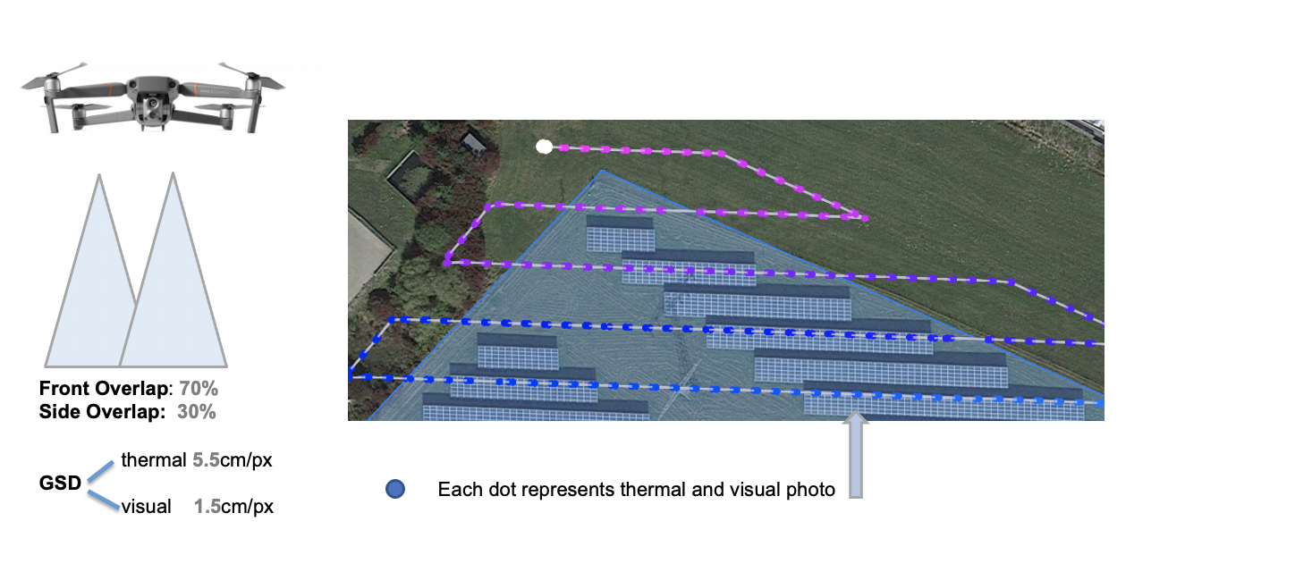
For the Solar Inspection Essential data product we require visual (RGB) and thermal photos. A drone pilot will use an unmanned aerial system (a drone with a camera) to capture the data on site.
The aerial data can be captured in two ways:
Using dual camera system as H20T/ XT2 where visual and thermal data are simultaneously recorded. The main setting is based on the thermal flight as the visual recording simply follows the thermal one.
* highly recommended for better quality & efficiency
Using separately visual a thermal system (separate setting)
Visual (RGB) Data Requirements
Ground Sample Distance (GSD): 1.0 - 1.5 cm per pixel at ground level.
Front Overlap (direction of the flight lines): 70%.
Side Overlap (perpendicular to the direction of the flight lines): 30%.
Flight Line Direction: Along the long edge of the solar rows.
Flight Path: At least 2 flight lines should be outside the boundaries of the operation in all directions.
Gimbal Orientation: standard Nadir (-90 deg), with acceptable deviation up to 20 deg to avoid sun glare.
Image Format: JPEG.
Each image should contain the following metadata: GPS location, relative altitude, gimbal pitch, gimbal yaw, gimbal roll and local timestamp.Image Quality: in focus, free from motion blur and minimal glare.
Thermal Data Requirements
GSD: 5.5 cm per pixel at panel level.
Front Overlap (direction of the flight lines): 70%.
Side Overlap (perpendicular to the direction of the flight lines): 30%.
Image Resolution: 640x512 pixels.
Flight Line Direction: Along the long edge of the solar rows.
Gimbal Orientation: standard Nadir (-90 deg), with acceptable deviation up to 20 deg to avoid sun glare.
Image format: R-JPEG or Radiometric TIF.
Each image should contain the following metadata: GPS location, relative altitude, gimbal pitch, gimbal yaw, gimbal roll and local timestamp.Image Quality: in focus, free from motion blur and minimal glare.
Environmental Conditions: Aim for clear blue sky. If a cloud passes, wait 10-15 minutes for the panels to heat up again. Successive flights should not exceed 15 minutes, unless it is a new flight block. Wind speed below 5 m/s, humidity ideally less than 60%.
Irradiance: ≥ 600 Watt/sqm 🔥
TRACKER SYSTEM:
Special Considerations for Single-Axis Trackers:
Trackers should be as horizontal as possible, up to a maximum 45 deg tilt. Avoid flying in the early morning or late afternoon when the sun is low at the horizon to minimise inter-row glare.Special Considerations for Double-Axis Trackers:
Trackers should be as horizontal as possible, up to a maximum 45 deg tilt. The entire tracker should be visible on at least one photo. Otherwise, increase the altitude.Rooftop: When collecting data from rooftop solar installations, please find some interesting flight tips here.
Demonstration when flying with dual camera (H20T, M2EA, XT2...)
❗️ Using dual camera system allows thermal and visual data to be simultaneously recorded. The main setting is based on the thermal flight as the visual recording is simply following the thermal one.
We highly recommend it for Enhanced Flight Quality Performance.
Blocks
To ensure weather conditions are kept homogeneous across the entire solar inspection, sites larger than 5ha should always be divided into separate blocks.
To ensure a consistent Ground Sample Distance [cm/pixel], sites with elevation differences of more than 10m should always be divided into separate blocks.
Blocks will have to be flown separately.
The SIDEREAL platform does not let you cut sites into blocks. Reach out to our support team at customer@siderealai.space to let them know and they will cut the site into blocks on your behalf.
Site As-Built
In the Solar Inspection Essential we identify the thermal anomalies using the raw data. In order to mark the anomalies on the map, we need an up-to-date, accurately geo-referenced as-built plan from your solar site. This should be uploaded on the SIDEREAL Fuse platform as a site overlay. The site as-built , like for example a detailed string plan, is crucial to ensure all of the geospatial data is mapped correctly.
⚠️ It's very important that you upload the solar site as-built (string plan) prior to the confirmation of the operation.
The as-built plan needs to meet the following requirements:
Should be recent to match the site as closely as possible.
Needs to show each individual solar panel.
Should be accurately scaled so it can be geo-referenced on the map.
Needs to show clear physical reference points, such as roads, buildings, rivers, tables, panels, etc..
Should be uploaded in PDF or DXF, as an overlay in SIDEREAL Fuse.
Should be uploaded prior to the confirmation of the operation.
It is important that, if there is only a PDF, some site reference points on the as-built must be visible on the satellite image in SIDEREAL Fuse. So it can be accurately geo-referenced on the map.Should cover all areas that need analysis, because areas not covered in the as-built might not be analysed.
Should not be hand-drawn or low-quality scanned site plans.
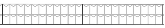
Some examples showing a good and a bad as-built plan.
✅ Good - every module is clearly visible.
❌ Not good - modules are not visible.
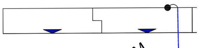
❌ Not Good - the resolution is too low, meaning that we can not use any reference point from the as-built to locate on the map.
DXF overlay requirements
The CAD drawing should be georeferenced as the EPSG needs to be provided on upload to the platform.
The CAD file cannot contain any blocks. If the panels/banks are in the drawing as a block then they need to be exploded into polylines. The platform does not support blocks.
Xrefs are not supported. Any Xrefs should be inserted in to the main CAD file.
There can be no hatches in the CAD file. The platform cannot display hatches.
The drawing should be purged before saving to remove un-required layers.
The CAD file needs to be provided as a DXF 2010 version.
The DXF should be <500MB.
At the moment text is not supported. Therefore any text within the DXF will not be displayed on the platform.
If you do not have an as-built from your site available, use the Solar Site As-built data product from SIDEREAL. We can help you to generate the as-built from your solar site. Please get in touch with your account manager or our customer@siderealai.space to get more information about this data product.
⚠️ If it's the first solar inspection on a specific site, we strongly recommend ordering a Solar Site As-built to have a high-quality georeferenced map of your solar site. This will also enhance your experience with the features on SIDEREAL Fuse platform.